
Mobile Shelving Dimensions and Capacity Guide
Use this guide to estimate mobile shelving dimensions and capacity before requesting a final archive-room layout. It explains room measurements, carriage dimensions, rows, bays, shelf levels, operating aisles and approximate linear filing capacity.
The calculations are useful for early planning and quotation preparation, but final rail positions, equipment dimensions, floor loading and project clearances should be confirmed on the approved drawing.
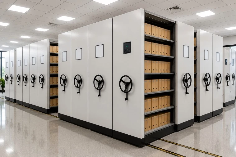
Final mobile shelving dimensions are confirmed according to the room plan, stored files, operating aisle, building conditions and approved project layout.
Measure These 8 Items Before Calculating Mobile Shelving Dimensions and Capacity
Room length and width alone are not enough. Doors, columns, services, floor conditions and stored-item dimensions can all reduce usable storage space.
Clear Internal Room Length
Measure finished wall to finished wall. Do not rely only on architectural drawings if wall linings, skirting or service boxes have already been installed.
Clear Internal Room Width
Record the narrowest usable width, especially where columns, wall projections or door swings reduce the nominal room dimension.
Finished Ceiling Height
Include lighting, sprinklers, air-conditioning ducts and other overhead services. Practical system height depends on room clearance and safe file access.
Door Position and Opening Direction
Record door width, swing direction and distance from the door to adjacent walls. Required access routes should remain clear.
Columns and Permanent Obstructions
Mark structural columns, radiators, electrical panels, pipework, fire equipment and other areas that must remain accessible.
Floor Level and Structural Condition
Confirm whether the floor is concrete, raised flooring or another construction. Structural suitability and allowable loading require project review.
File, Box or Media Dimensions
Provide the height, depth and approximate width of stored materials. Archive boxes, binders, folders and books require different shelf spacing.
Current Quantity and Future Growth
State current linear filing length, box quantity or file quantity together with the expected growth period. Planning only for current records can make the archive undersized soon after installation.
What Does “Linear Filing Metres” Mean?
Linear filing metres describe the total usable horizontal shelf length available for placing files, folders, books or archive boxes side by side.
It is a capacity measurement—not the physical length of the mobile shelving system itself.
One shelf with 900 mm clear usable width provides approximately 0.9 linear metres.
Five usable levels within one bay face provide approximately 4.5 linear metres.
At 0.9 m clear width, one four-bay storage face provides approximately 18 linear metres.
Linear metres allow archive capacity to be compared more reliably than simply counting cabinets or mobile rows.
Room Dimensions and Mobile Shelving Dimensions Are Not the Same
The room area must first be reduced by operational clearances, building obstructions and required access zones before the usable shelving footprint is calculated.
Carriage length is normally formed by several shelving bays positioned side by side. Wall clearance and room access reduce the maximum usable run.
Fixed rows, movable carriages and the required operating aisle must all fit within the available system depth.
Additional shelf levels increase capacity only when the stored material remains accessible and adequate top clearance is maintained.
Preliminary calculations are useful for comparison and budgeting, but rail positions, clearances, loading and equipment dimensions should be confirmed before production.
How to Calculate Approximate Mobile Shelving Capacity
Mobile shelving capacity is most useful when expressed as linear filing metres. The estimate should use clear usable shelf width rather than external equipment width.
Calculate Bays per Storage Face
Divide the usable carriage length by the selected bay width and round down to the complete quantity that fits.
Calculate Storage Faces
A double-sided movable carriage normally provides two storage faces. A single-sided fixed row normally provides one.
Calculate Shelf Runs
Multiply storage faces by bays per face and the number of shelf levels actually used for filing.
Calculate Linear Filing Capacity
Multiply total shelf runs by clear internal shelf width.
Illustrative Archive Room
The figures below demonstrate the calculation method only. They are not a universal product specification or a final engineering layout.
Storage Faces
6 movable carriages × 2 faces + 1 fixed face = 13 storage faces.
Accessible Bay Faces
13 storage faces × 4 bays per face = 52 accessible bay faces.
Total Shelf Runs
52 bay faces × 5 active shelf levels = 260 shelf runs.
Linear Filing Metres
260 shelf runs × 0.9 m clear shelf width = 234 linear metres.
Actual usable capacity may be lower after dividers, end stops, handling clearance, special accessories and final project dimensions are confirmed.
Mobile Shelving Dimensions and Capacity: Preliminary Reference Ranges
The ranges below are intended for preliminary room planning. Final dimensions, load capacity, aisle width, rail arrangement and system clearances should be confirmed for each project.
| Planning Item | Typical Preliminary Range | What Changes the Dimension | Project Check |
|---|---|---|---|
| Bay width | Approximately 800–1,200 mm | File format, shelf loading, room dimensions and selected shelving configuration | Confirm clear internal shelf width |
| Single-sided shelf depth | Approximately 250–600 mm | Folders, archive boxes, books, binders or special stored items | Use actual stored-item depth as the basis |
| Double-sided carriage depth | Project-specific according to shelf depth and central structure | Two shelf faces, upright design and back-to-back configuration | Confirm external carriage depth on drawing |
| Operating aisle | Project-specific; preliminary concepts often start around 800–1,200 mm | User access, trolley use, workflow, accessibility and local requirements | Confirm required clear aisle width |
| Shelf pitch | Approximately 25 or 50 mm adjustment systems may be used depending on upright design | File height, box height and selected shelving structure | Measure actual stored materials |
| Active shelf levels | Commonly approximately 4–8 levels | System height, stored-item height and practical access | Do not count unusable top clearance |
| Shelf load | Approximately 40–120 kg UDL depending on selected shelf structure | Shelf span, structural configuration and stored material | Confirm required load before quotation |
| System height | Approximately 1,800–2,600 mm | Ceiling height, stored-item dimensions and practical access | Confirm finished clear room height |
| Wall and end clearances | Determined by room and installation conditions | Walls, skirting, handles, drives, tolerances and maintenance access | Confirm on approved layout |
These figures are general planning references only. Building requirements, floor loading, fire access, accessibility and system engineering requirements vary by project and location.
How Different Row Arrangements Affect Mobile Shelving Capacity
The highest possible row count does not automatically create the best archive. Access frequency, room shape, workflow and reserve capacity should also influence the layout.
Single Operating Aisle
Most movable rows remain together while one working aisle is opened where access is required. This supports high storage density in controlled-access archives.
Multiple Access Zones
Separate access zones can improve workflow for departments or user groups, but additional permanently open space reduces total storage density.
Fixed End Rows with Movable Centre Rows
Fixed wall-side or end rows can use boundary space while movable rows create the high-density central storage zone.
Factors That Reduce Final Usable Filing Capacity
A theoretical calculation assumes every shelf is fully usable. Real archive rooms normally lose some capacity to handling clearance, accessories, mixed file sizes and building constraints.
File Handling Clearance
Files need enough free height to be removed and returned without scraping the shelf above.
Dividers and End Stops
Dividers improve organization but occupy a small amount of clear shelf length.
Mixed File Sizes
Tall archive boxes may force greater shelf spacing across part of the system.
Restricted Building Areas
Fire equipment, electrical panels, columns, doors and access routes reduce usable footprint.
Future Growth Reserve
Reserved future capacity should not be treated as currently occupied filing capacity.
Special Accessories
Drawers, hanging rails, pull-out components and specialized storage accessories use space differently from standard shelves.
Capacity Calculation Is Not Structural Approval
A preliminary capacity calculation cannot confirm that a floor or building is suitable for a fully loaded mobile shelving system.
- Floor load capacity should be verified by the responsible building professional.
- Rail fixing and floor construction must suit the selected installation method.
- Required escape, fire and access routes should remain unobstructed.
- Final equipment loading should be based on the approved system configuration.
- Local project requirements may require additional clearances or safety provisions.
Information to Send SAS for a Preliminary Layout
A complete project brief reduces repeated revisions and allows the first proposal to reflect the actual room, stored materials and future capacity target.
Common Mobile Shelving Dimensions and Capacity Planning Errors
Many early layout errors come from confusing nominal equipment dimensions with clear usable dimensions.
Using External Bay Width as Usable Shelf Length
Uprights and structural components can reduce clear internal shelf width. Filing capacity should use the actual usable shelf dimension.
Ignoring Doors and Wall Obstructions
A system may fit mathematically but interfere with doors, columns, electrical equipment or required maintenance access.
Counting Every Shelf Level as Fully Usable
Top clearances, file handling space and mixed record heights can make some theoretical shelf positions impractical.
Planning Only for Current Archive Volume
Without future reserve capacity, a newly installed archive may become full much earlier than expected.
Choosing the Narrowest Possible Aisle
The operating aisle should suit actual users, trolleys, retrieval workflow and applicable project requirements.
Confirming Equipment Before Reviewing the Floor
High-density storage concentrates loaded weight. Floor conditions and structural suitability should be reviewed before final system approval.
Choose Manual, Electric or Smart Operation After the Layout Is Defined
Manual, electric and smart mobile shelving follow similar dimensional planning principles. The main differences concern operation, control, safety functions and project complexity.
Manual Mobile Shelving System
Handwheel-driven movement for archive rooms requiring high-density storage with straightforward mechanical operation.
- No electrical drive required for normal movement
- Suitable for moderate-access archives
- Lower control complexity
Electric Mobile Shelving System
Motor-driven aisle opening for projects requiring easier movement and more frequent archive access.
- Motorized row movement
- Push-button or touchscreen control according to configuration
- Project-confirmed safety functions
Smart Mobile Shelving System
A higher-level control option for projects requiring touchscreen operation, visible status, configured permissions or other approved management functions.
- Touchscreen control interface
- Configured access and status functions where specified
- Project-specific integration options where technically approved
Mobile Shelving Dimensions and Capacity FAQ
What are typical mobile shelving dimensions?
What is the standard width of a mobile shelving bay?
How wide should a mobile shelving operating aisle be?
How is mobile shelving capacity measured?
What does 100 linear metres of storage mean?
Does a double-sided carriage provide twice the storage faces of a single-sided row?
Can room area alone determine final mobile shelving capacity?
How much future growth capacity should be included?
Can SAS prepare a layout from a room drawing?
Send Your Room Dimensions for a Preliminary Mobile Shelving Layout
SAS can review available space, archive quantity, stored-item dimensions and access requirements to prepare a preliminary capacity calculation and project-specific configuration for manual, electric or smart mobile shelving.
- Clear room length, width and height
- Door, column and obstruction positions
- File, folder or archive-box dimensions
- Current quantity or existing linear shelf length
- Expected future growth
- Required shelf loading and accessories
- Manual, electric or smart operation preference